1,目的。
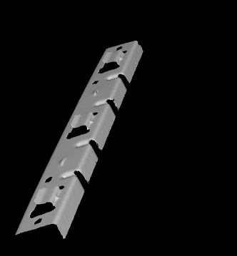
- 测量3D翼片的距离与角度。
- 说明:
- 标注A 红色框选的区域即为
翼片,本示例的3D 对象共有3个翼片待测。 L1与L2的距离、L1与L2的角度即为所求的翼片距离与角度。
- 标注A 红色框选的区域即为


2,原理。
- 使用线结构光模型(标定模式)获取作为参考对象的 3D 点云,以及结构光模型默认的
lightPlanepose,movementpose。 - 使用三个光平面与 作为参考对象的 3D 点云对象相交,获取光平面与 3D 对象的交集点云,将该交集点云投影到2D 平面形成轮廓。
- 筛选出所需的轮廓
L1与L2,求出3组L1与L2的距离均值,角度均值,将该值作为标准值。 - 使用结构光模型获取被测的 3D 点云,并将该3D点云与参考对象的3D点云进行表面匹配获取Pose。
- 对三个光平面进行刚体变化,保证光平面与被测的3D点云相切,获取切平面。
- 对被测对象的切平面进行投影,筛选出轮廓,计算轮廓的距离与角度是否在规定的范围内。
3,程序解析。
3.1,创建参考 3D 对象样本。
* 参考案例库:inspect_3d_surface_intersections.hdev* 目的:测量三个金属薄片翅凸起的角度与距离*
* ------------Part01,建立参考 3D 对象样本* 1.1,配置线性结构光模型。
* 模式为‘calibration’,该模式将生成默认的lightpanelpose与movementpose,如果缺省则这两个位姿为空
NumDisparityProfiles := 441
read_image (DisparityProfile, 'sheet_of_light/metal_part_1_disparity_line_000')
create_sheet_of_light_model (DisparityProfile, 'calibration', 'offset_scale', SheetOfLightModelID)
* 设置校准方法‘offset_scale’的缩放因子
* 使得重建的三维物体模型近似给出
* 单位毫米
ScaleX := 1
ScaleY := 4
ScaleZ := 0.5
set_sheet_of_light_param (SheetOfLightModelID, 'scale_x', ScaleX)
set_sheet_of_light_param (SheetOfLightModelID, 'scale_y', ScaleY)
set_sheet_of_light_param (SheetOfLightModelID, 'scale_z', ScaleZ)
*
* 1.2,定义物体背景 z 轴分界值
MinZ := 220
*
* Initialize display
dev_update_off ()
set_system ('clip_region', 'false')
dev_close_window ()
get_image_size (DisparityProfile, DisparityProfileWidth, DisparityProfileHeight)
WindowEnlargement := 350
WindowWidth := DisparityProfileWidth + WindowEnlargement
WindowHeight := NumDisparityProfiles
dev_open_window (0, 0, WindowWidth, WindowHeight, 'black', WindowHandle)
dev_set_part (0, 0, WindowHeight - 1, WindowWidth - 1)
get_part (WindowHandle, PartRow1, PartColumn1, PartRow2, PartColumn2)
set_display_font (WindowHandle, 16, 'mono', 'true', 'false')
dev_set_draw ('fill')
*
* 1.3,定义一些可视化参数
VisualizationPlaneSize := 150
VisualizationCamParam := [0.01,0,6e-6,6e-6,WindowWidth / 2,WindowHeight / 2,WindowWidth,WindowHeight]
VisualizationPose := [-1550,680,5390,122,1,357,0]
VisualizationColors := ['magenta','blue','orange']
*
* 1.4,通过收集测量值来创建参考样本
* 通过 线激光测量模型 将视差轮廓转换为3D对象模型
gen_image_const (DisparityImageVis, 'uint2', DisparityProfileWidth, NumDisparityProfiles)
for Index := 0 to NumDisparityProfiles - 1 by 1* Add the next disparity profile to the sheet of light modelread_image (ImageModel, 'sheet_of_light/metal_part_1_disparity_line_' + Index$'03d')set_profile_sheet_of_light (ImageModel, SheetOfLightModelID, [])* Accumulated profiles for visualizationget_grayval (ImageModel, gen_tuple_const(DisparityProfileWidth,0), [0:DisparityProfileWidth - 1], Disparities)set_grayval (DisparityImageVis, gen_tuple_const(DisparityProfileWidth,Index), [0:DisparityProfileWidth - 1], Disparities)if (Index % 5 == 4)dev_display (DisparityImageVis)Message := 'Disparity image of the reference sample'Message[1] := 'Adding disparity profile ' + (Index + 1) + '/' + NumDisparityProfilesdisp_message (WindowHandle, Message, 'window', 12, 12, 'black', 'true')endif
endfor* 1.5,显示引用样本的视差图像
dev_display (DisparityImageVis)
stop ()
disp_message (WindowHandle, '引用样本的视差图', 'window', 12, 12, 'black', 'true')* 1.6,获取标定测量的三维对象(参考样本对象)
get_sheet_of_light_result_object_model_3d (SheetOfLightModelID, Model3DFull)* 最小外接长方体(min_x, min_y, min_z, max_x, max_y, max_z)。此属性长度为 6。
get_object_model_3d_params (Model3DFull, 'bounding_box1', BoundingBox1)* 1.7,去除背景后的样本 3D 对象
MaxZ := BoundingBox1[5]
select_points_object_model_3d (Model3DFull, 'point_coord_z', MinZ, MaxZ, Model3D)
clear_object_model_3d (Model3DFull)
disp_continue_message (WindowHandle, 'black', 'true')
stop ()
*
* Prepare the 3D object model for the intersection with
* the planes and to allow the alignment of the intersection
* planes to the objects to be inspected
dev_clear_window ()
dev_set_part (PartRow1, PartColumn1, PartRow2, PartColumn2)* 1.8,显示去除背景后的 3D 引用
disp_object_model_3d (WindowHandle, Model3D, VisualizationCamParam, VisualizationPose, [], [])
Message := '准备参考模型'
Message[1] := ' - triangulate 3D object model and'
Message[2] := ' - create surface model for alignment'
disp_message (WindowHandle, Message, 'window', 12, 12, 'black', 'true')* 1.9,计算 3D 模型的法线,并将法线信息附加到输入的模型
surface_normals_object_model_3d (Model3D, 'mls', 'mls_force_inwards', 'true', ObjectModel3DNormals)* 1.10,将离散的点数数据转换为三角网格模型
triangulate_object_model_3d (ObjectModel3DNormals, 'greedy', 'greedy_remove_small_surfaces', 200, ObjectModel3DReference, Information)
clear_object_model_3d (Model3D)
clear_object_model_3d (ObjectModel3DNormals)
释疑解析:
-
surface_normals_object_model_3d (Model3D, 'mls', 'mls_force_inwards', 'true', ObjectModel3DNormals)用于计算3D物体模型的表面法线,具体参数解析如下:
- 核心功能:
- 采用移动最小二乘法(MLS)计算3D点云数据的曲面法线
- 输出带法线信息的3D对象模型(ObjectModel3DNormals)
- 关键参数说明:
Model3D:输入3D点云模型句柄'mls':当前唯一支持的法线计算方法mls_force_inwards':强制法线指向模型内部的控制参数'true':启用上述强制内指功能
- 技术原理:
通过MLS算法对每个点的k邻域拟合曲面(平面或高阶多项式),计算投影点的法线方向。当启用mls_force_inwards时,系统会调整法线方向使其一致指向模型内部。
- 核心功能:
-
triangulate_object_model_3d (ObjectModel3DNormals, 'greedy', 'greedy_remove_small_surfaces', 200, ObjectModel3DReference, Information)用于将3D点云数据转换为三角网格模型,具体参数解析如下:
- 核心功能:
- 采用贪心算法(greedy)进行曲面重建
- 可移除表面积小于指定阈值的小面片
- 输出三角化后的3D模型(ObjectModel3DReference)和重建信息(Information)
- 关键参数说明:
ObjectModel3DNormals:输入带法线的3D模型句柄'greedy':指定使用贪心三角化算法'greedy_remove_small_surfaces':小面片过滤功能开关200:面积阈值(单位取决于输入模型),小于该值的面片将被移除
- 技术特点:
- 贪心算法通过迭代连接最近邻点形成三角形,效率较高但可能丢失细节
- 法线信息可提高重建准确性
- 小面片过滤能有效去除噪声和离群点
- 核心功能:
3.2,创建表面匹配模型,切平面位姿
*---------------------Part02,创建表面匹配模型,翼片的切平面位姿* 2.1,Create a surface model for alignment
create_surface_model (ObjectModel3DReference, 0.03, 'model_invert_normals', 'true', SurfaceModelID)
*
* 2.2,定义与翼片相切的位姿,平面
create_pose (300, 230, 250, -90, 0, 0, 'Rp+T', 'gba', 'point', PoseIntersectionPlane1)
create_pose (300, 900, 250, -90, 0, 0, 'Rp+T', 'gba', 'point', PoseIntersectionPlane2)
create_pose (300, 1570, 250, -90, 0, 0, 'Rp+T', 'gba', 'point', PoseIntersectionPlane3)
gen_plane_object_model_3d (PoseIntersectionPlane1, [-1,-1,1,1] * VisualizationPlaneSize, [-1,1,1,-1] * VisualizationPlaneSize, IntersectionPlane1)
gen_plane_object_model_3d (PoseIntersectionPlane2, [-1,-1,1,1] * VisualizationPlaneSize, [-1,1,1,-1] * VisualizationPlaneSize, IntersectionPlane2)
gen_plane_object_model_3d (PoseIntersectionPlane3, [-1,-1,1,1] * VisualizationPlaneSize, [-1,1,1,-1] * VisualizationPlaneSize, IntersectionPlane3)
dev_clear_window ()
dev_set_part (PartRow1, PartColumn1, PartRow2, PartColumn2)* 2.3,显示样本 3D 对象与与之相切的切平面
disp_object_model_3d (WindowHandle, [ObjectModel3DReference,IntersectionPlane1,IntersectionPlane2,IntersectionPlane3],VisualizationCamParam,VisualizationPose, ['color_1','color_2','color_3','alpha','alpha_0','disp_pose'], [VisualizationColors,0.75,1,'true'])
Message := 'Reference sample with predefined intersection planes'
* 正则表达式替换
MessageWrapped := regexp_replace(Message + ' ',['(.{0,25})\\s','replace_all'],'$1\n')
disp_message (WindowHandle, MessageWrapped, 'window', 12, 12, 'black', 'true'
显示效果:

3.3,计算 样本 翼片组的距离均值与角度均值(重点)
* ----------------------Part03,计算 样本 翼片组的距离与角度,推导出距离与角度的标准值* 3.1,获取样本 3D 对象切平面的点云
intersect_plane_object_model_3d (ObjectModel3DReference, PoseIntersectionPlane1, ObjectModel3DIntersection1)
intersect_plane_object_model_3d (ObjectModel3DReference, PoseIntersectionPlane2, ObjectModel3DIntersection2)
intersect_plane_object_model_3d (ObjectModel3DReference, PoseIntersectionPlane3, ObjectModel3DIntersection3)
*
* 3.2,投影翼片切平面点云获取切平面XLD轮廓
project_object_model_3d_lines_to_contour_xld (Intersection1, PoseIntersectionPlane1, ObjectModel3DIntersection1)
project_object_model_3d_lines_to_contour_xld (Intersection2, PoseIntersectionPlane2, ObjectModel3DIntersection2)
project_object_model_3d_lines_to_contour_xld (Intersection3, PoseIntersectionPlane3, ObjectModel3DIntersection3)
*
* Clean up memory
clear_object_model_3d ([ObjectModel3DIntersection1,ObjectModel3DIntersection2,ObjectModel3DIntersection3])
*
* 3.3,筛选提取旋转角度为20±15的轮廓
OrientationRef := 20
OrientationTolerance := 15* 3.4,分析计算表示翼片的轮廓之间距离与角度
* Intersection1,投影出来的翼片轮廓; FittedLines1:拟合的翼片上线下线轮廓
analyze_intersection (Intersection1, FittedLines1, OrientationRef, OrientationTolerance, MinDistance1, MaxDistance1, Angle1)
analyze_intersection (Intersection2, FittedLines2, OrientationRef, OrientationTolerance, MinDistance2, MaxDistance2, Angle2)
analyze_intersection (Intersection3, FittedLines3, OrientationRef, OrientationTolerance, MinDistance3, MaxDistance3, Angle3)
*
* Visualize the object with the intersection planes and the respective
* intersections and measurement results
hom_mat2d_identity (HomMat2DIdentity)* 3.5 ,显示测量结果
Message := 'Intersections with measurement lines'
MessageWrapped := regexp_replace(Message + ' ',['(.{0,20})\\s','replace_all'],'$1\n')
disp_message (WindowHandle, MessageWrapped, 'window', 12, 330, 'black', 'true')
Message := 'Measurement results'
MessageWrapped := regexp_replace(Message + ' ',['(.{0,20})\\s','replace_all'],'$1\n')
disp_message (WindowHandle, MessageWrapped, 'window', 12, 590, 'black', 'true')* 显示第1个翼片测量数据
hom_mat2d_translate (HomMat2DIdentity, 350, 390, HomMat2DTranslate1)
* 仿射变化相交的轮廓
affine_trans_contour_xld (Intersection1, Intersection1Vis, HomMat2DTranslate1)
* 仿射变化作为上线与下线的轮廓
affine_trans_contour_xld (FittedLines1, FittedLines1Vis, HomMat2DTranslate1)
dev_set_color (VisualizationColors[0])
dev_set_line_width (5)
dev_display (Intersection1Vis)
dev_set_color ('white')
dev_set_line_width (1)
dev_display (FittedLines1Vis)
Message := 'Angle        = ' + Angle1$'.1f' + ' deg'
Message[1] := 'Min Distance = ' + MinDistance1$'.1f' + ' mm'
Message[2] := 'Max Distance = ' + MaxDistance1$'.1f' + ' mm'
disp_message (WindowHandle, Message, 'window', 310, 600, VisualizationColors[0], 'false')* 显示第2个翼片测量数据
hom_mat2d_translate (HomMat2DIdentity, 250, 410, HomMat2DTranslate2)
affine_trans_contour_xld (Intersection2, Intersection2Vis, HomMat2DTranslate2)
affine_trans_contour_xld (FittedLines2, FittedLines2Vis, HomMat2DTranslate2)
dev_set_color (VisualizationColors[1])
dev_set_line_width (5)
dev_display (Intersection2Vis)
dev_set_color ('white')
dev_set_line_width (1)
dev_display (FittedLines2Vis)
Message := 'Angle        = ' + Angle2$'.1f' + ' deg'
Message[1] := 'Min Distance = ' + MinDistance2$'.1f' + ' mm'
Message[2] := 'Max Distance = ' + MaxDistance2$'.1f' + ' mm'
disp_message (WindowHandle, Message, 'window', 210, 600, VisualizationColors[1], 'false')* 显示第3个翼片测量数据
hom_mat2d_translate (HomMat2DIdentity, 150, 430, HomMat2DTranslate3)
affine_trans_contour_xld (Intersection3, Intersection3Vis, HomMat2DTranslate3)
affine_trans_contour_xld (FittedLines3, FittedLines3Vis, HomMat2DTranslate3)
dev_set_color (VisualizationColors[2])
dev_set_line_width (5)
dev_display (Intersection3Vis)
dev_set_color ('white')
dev_set_line_width (1)
dev_display (FittedLines3Vis)
Message := 'Angle        = ' + Angle3$'.1f' + ' deg'
Message[1] := 'Min Distance = ' + MinDistance3$'.1f' + ' mm'
Message[2] := 'Max Distance = ' + MaxDistance3$'.1f' + ' mm'
disp_message (WindowHandle, Message, 'window', 110, 600, VisualizationColors[2], 'false')
disp_continue_message (WindowHandle, 'black', 'true')
stop ()
*
* 3.6,根据样本三个翼片测量结果,推导出的标准参数* ======推导出的翼片标准参数
AngleRef := mean([Angle1,Angle2,Angle3])
* 角度的容差范围
MaxAngleDev := 2
* 许可的最小角度值
MinAngle := AngleRef - MaxAngleDev
* 许可的最大角度
MaxAngle := AngleRef + MaxAngleDev
* 许可的最大距离
MinDistance := 0.95 * mean([MinDistance1,MinDistance2,MinDistance3])
* 许可的最小距离
MaxDistance := 1.05 * mean([MaxDistance1,MaxDistance2,MaxDistance3])
* Display the nominal dimensions and the tolerance limits
dev_clear_window ()
Message := 'Tolerance limits for the angle and the distance of the mounting tabs, derived from the three measurements on the reference sample:'
MessageWrapped := regexp_replace(Message + ' ',['(.{0,75})\\s','replace_all'],'$1\n')
Message := MessageWrapped
Message[1] := ' '
Message[2] := 'Min Angle    = ' + MinAngle$'.1f' + ' deg'
Message[3] := 'Max Angle    = ' + MaxAngle$'.1f' + ' deg'
Message[4] := ' '
Message[5] := 'Min Distance = ' + MinDistance$'.1f' + ' mm'
Message[6] := 'Max Distance = ' + MaxDistance$'.1f' + ' mm'
disp_message (WindowHandle, Message, 'window', 12, 12, 'black', 'true')
disp_continue_message (WindowHandle, 'black', 'true')
stop ()
*======================
效果图:


本地函数:
1,project_object_model_3d_lines_to_contour_xld
作用: 将 3D对象 投影为xld轮廓。
* PoseIntersectionPlane:切平面在世界坐标系的位姿
* PoseInvert:在切平面位置有一个虚拟相机,这个就是这个虚拟相机的位姿(外参)
* 也就是世界坐标系在虚拟相机的相机坐标系的位姿
pose_invert (PoseIntersectionPlane, PoseInvert)* 确保投影平面在虚拟的正前方
* 获取三维对象模型沿坐标轴对齐的包围盒的对角线长度,即包围盒的直径。
* 因为虚拟相机和切平面点云重合所有为了投影成像需要将该虚拟相机沿z轴进行偏移
get_object_model_3d_params (ObjectModel3DIntersection, 'diameter_axis_aligned_bounding_box', Diameter)PoseInvert[2] := PoseInvert[2] + Diameter* 3,虚拟相机的内参。
*========================
* 相机内参参数组成:*Focus:相机的焦距,如果是远心相机,则焦距为0*Kappa:畸变系数,初始值可以设置为0*Sx、Sy:单个像元的宽,高(可从相机说明书中获取)*Cx、Cy:图像的原点坐标,初始值可认为是图像的中心点,即坐标分为为图像的宽度和高度的一半*ImageWidth,ImageHeight:采集图像的宽和高*===========================
* Focus:=0:表示虚拟相机无透视缩放仅为平行投影
* 虚拟相机不需要畸变所以 Kappa:=0;
*  Sx,Sy:=1,不进行缩放按照原图大小输出
* 使用平行投影来实现所需的缩放(默认为1:1)
* CamParam为虚拟相机的内参
Scale := 1
CamParam := [0,0,1.0 / Scale,1.0 / Scale,0,0,512,512]
* 4,投影获取xld轮廓。
project_object_model_3d (Intersection, ObjectModel3DIntersection, CamParam, PoseInvert, 'data', 'lines')
return ()
释疑解惑:
为什么需要PoseInvert[2] := PoseInvert[2] + Diameter?
- 避免物体遮挡投影
- 当投影平面与物体位置重叠时,投影结果可能因物体自身遮挡而丢失部分几何信息。例如,若投影平面位于物体内部,部分表面会被遮挡,导致轮廓线残缺。
- 通过沿z轴正方向平移投影平面(如代码中
PoseInvert[2] += Diameter),可使投影平面位于物体包围盒之外,从而完整捕捉物体的可见边界。
- 平行投影的几何精度保障
- 平行投影需保持严格的比例关系(如默认1:1缩放)。若投影平面与物体距离过近,可能导致坐标溢出或畸变,尤其在物体跨越坐标系原点时。
- 平移后,投影平面与物体间形成安全距离(通常为包围盒直径),确保物体所有顶点坐标均位于相机视锥体内,避免裁剪错误。
- 三维坐标系变换的物理意义
- 位姿逆变换
pose_invert将物体从世界坐标系转换到投影平面坐标系。此时投影平面默认位于新坐标系的原点(即原平面位置),可能导致投影平面与物体空间重叠。 - 沿z轴平移可理解为将投影平面从“观察者视角的原点”移至“观察者前方”,符合人类视觉感知习惯。
- 位姿逆变换
- 正交投影的规范化需求
- 规范化坐标系要求投影范围限定在合理区间(如[-1,1])。若投影平面距离过近,物体坐标可能超出该范围,导致投影结果失真或不可控。
- 调整z轴位置可对物体坐标进行归一化处理,满足图形API(如OpenGL/Direct3D)的标准化视口要求。
运算获取的轮廓Intersection示例:

2,analyze_intersection
作用: 筛选符合条件的轮廓片段,对符合条件的轮廓片段进行拟合,计算彼此间的距离、角度。
* selected and grouped.
*
* Cut the contour into segments
segment_contours_xld (Intersection, ContoursSplit, 'lines_circles', 7, 3, 2)
* Select the segments that have approximately the expected orientation
select_shape_xld (ContoursSplit, SelectedXLD, ['orientation_points','orientation_points'], 'or', rad([OrientationRef,OrientationRef - 180]) - rad(OrientationTolerance), rad([OrientationRef,OrientationRef - 180]) + rad(OrientationTolerance))
* Select the three longest segments
length_xld (SelectedXLD, Length)
SelectedId := sort_index(-Length)[0:2] + 1
* 最长的片段
select_obj (SelectedXLD, ObjectSelected1, SelectedId[0])
* 第2长的片段
select_obj (SelectedXLD, ObjectSelected2, SelectedId[1])
* 第3长的片段
select_obj (SelectedXLD, ObjectSelected3, SelectedId[2])
* 计算三个片段的两两距离
* to decide, which of them represents the mounting tab
distance_cc_min (ObjectSelected1, ObjectSelected2, 'fast_point_to_segment', DistanceMin12)
distance_cc_min (ObjectSelected1, ObjectSelected3, 'fast_point_to_segment', DistanceMin13)
distance_cc_min (ObjectSelected2, ObjectSelected3, 'fast_point_to_segment', DistanceMin23)
* 两两距离最大的 距离索引
LargestDistId := sort_index(-[DistanceMin12,DistanceMin13,DistanceMin23])[0]
switch (LargestDistId)
case 0:* 片段1 与 片段2 的距离是最大时:concat_obj (ObjectSelected1, ObjectSelected2, GroundPlane)copy_obj (ObjectSelected3, MountingTab, 1, 1)break
case 1:* 片段1 与 片段3 的距离是最大时:concat_obj (ObjectSelected1, ObjectSelected3, GroundPlane)copy_obj (ObjectSelected2, MountingTab, 1, 1)break
case 2:*片段2 与 片段3 的距离是最大时:concat_obj (ObjectSelected2, ObjectSelected3, GroundPlane)copy_obj (ObjectSelected1, MountingTab, 1, 1)break
endswitch
*
* 两个片段距离最大时,则认为这两个片段延长线是共线(翼片底线)
union_adjacent_contours_xld (GroundPlane, GroundPlaneUnion, 1000, 50, 'attr_keep')
* 拟合翼片底线
fit_line_contour_xld (GroundPlaneUnion, 'tukey', -1, 0, 5, 2, RowBegin, ColBegin, RowEnd, ColEnd, Nr, Nc, Dist)
if (ColEnd < ColBegin)* Reverse the orientation of the lineT := ColEndColEnd := ColBeginColBegin := TT := RowEndRowEnd := RowBeginRowBegin := TNr := -NrNc := -Nc
endif
* 计算出的上线
gen_contour_polygon_xld (Contour, [RowBegin,RowEnd], [ColBegin,ColEnd])
*  MoutingTab 是与 另外两个共线的片段 不共线的片段
fit_line_contour_xld (MountingTab, 'tukey', -1, 0, 5, 2, RowBeginMT, ColBeginMT, RowEndMT, ColEndMT, NrMT, NcMT, DistMT)
if (ColEndMT < ColBeginMT)* Reverse the orientation of the lineT := ColEndMTColEndMT := ColBeginMTColBeginMT := TT := RowEndMTRowEndMT := RowBeginMTRowBeginMT := TNrMT := -NrMTNcMT := -NcMT
endif
* 计算出的下线
gen_contour_polygon_xld (ContourMT, [RowBeginMT,RowEndMT], [ColBeginMT,ColEndMT])
* 连接上线 与 下线
concat_obj (ContourMT, Contour, FittedLines)
*
* Calculate the opening width and the angle
distance_pl ([RowBeginMT,RowEndMT], [ColBeginMT,ColEndMT], RowBegin, ColBegin, RowEnd, ColEnd, Distances)
MinDistance := min(Distances)
MaxDistance := max(Distances)
* 上线法向量与下线法向量的夹角
angle_ll (0, 0, NrMT, NcMT, 0, 0, Nr, Nc, AngleRad)
Angle := deg(AngleRad)
* Wrap the absolute angle to 90 deg or less
if (Angle < -90)Angle := Angle + 180
elseif (Angle > 90)Angle := Angle - 180
endif
*
return ()
释疑解惑:
select_shape_xld算子使用orientation与orientation_points作为筛选特征时,有何差异?
- 计算原理差异
| 特征 | orientation参数 | orientation_points参数 |
|---|---|---|
| 几何基础 | 基于等效椭圆主轴方向或外接矩形方向计算 | 基于离散点集拟合主方向(类似点云处理) |
| 轮廓依赖性 | 依赖轮廓顺序和几何完整性 | 忽略轮廓顺序,仅分析点集分布 |
| 自相交兼容性 | 仅适用于非自交轮廓 | 支持自相交轮廓 |
- 参数行为差异
- 角度范围处理
orientation返回-π/2 < Phi ≤ π/2,需通过OrientationRef - 180覆盖所有方向orientation_points返回-π ≤ Phi < π,直接支持全角度范围判断
- 筛选逻辑实现
注:两者均通过* orientation版本(非自交轮廓适用) select_shape_xld(ContoursSplit, SelectedXLD, ['orientation','orientation'], 'or', rad([OrientationRef,OrientationRef-180])-rad(OrientationTolerance),rad([OrientationRef,OrientationRef-180])+rad(OrientationTolerance)) :ml-citation{ref="3" data="citationList"}* orientation_points版本(自交轮廓适用) select_shape_xld(ContoursSplit, SelectedXLD, ['orientation_points','orientation_points'], 'or',rad([OrientationRef,OrientationRef-180])-rad(OrientationTolerance),rad([OrientationRef,OrientationRef-180])+rad(OrientationTolerance)) :ml-citation{ref="3" data="citationList"}'or'逻辑合并OrientationRef和OrientationRef-180的容忍区间,但底层计算方式不同 - 角度范围处理
- 应用场景对比
| 场景 | 推荐参数 | 原因 |
|---|---|---|
| 规则几何体筛选 | orientation | 依赖几何主轴方向,结果更稳定(如矩形零件方向检测) |
| 自交轮廓处理 | orientation_points | 避免因轮廓自交导致方向误判(如复杂多边形或点云数据) |
| 抗噪需求高 | orientation_points | 对离散点噪声更鲁棒(需配合test_self_intersection_xld检测) |
- 返回值验证建议
- 使用
test_self_intersection_xld检测轮廓自交性 - 自交轮廓优先选择
orientation_points,否则使用orientation - 通过
get_shape_xld算子验证实际返回的角度值范围是否符合预期
- 使用
本地函数运行效果:

3.4,对被测 3D 对象进行测量
* --------------------------Part 4:对点云对象进行测量
*
*
* Inspection loop
NumScenes := 4* 4.1,通过线结构光模型获取待测的 3D 对象
for SceneIndex := 1 to NumScenes by 1dev_clear_window ()dev_set_part (PartRow1, PartColumn1, PartRow2, PartColumn2)* Reset 线结构光测量模型的 视差图 ; 所有其他设置都可以重用reset_sheet_of_light_model (SheetOfLightModelID)* * Create the test object by collecting the measured* disparity profiles in a sheet-of-light model and* transforming them to a 3D object modelgen_image_const (DisparityImageVis, 'uint2', DisparityProfileWidth, NumDisparityProfiles)for Index := 0 to NumDisparityProfiles - 1 by 1* Add the next disparity profile to the sheet of light modelread_image (ImageSearch, 'sheet_of_light/metal_part_' + (SceneIndex + 1) + '_disparity_line_' + Index$'03d')set_profile_sheet_of_light (ImageSearch, SheetOfLightModelID, [])* Accumulated profiles for visualizationget_grayval (ImageSearch, gen_tuple_const(DisparityProfileWidth,0), [0:DisparityProfileWidth - 1], Disparities)set_grayval (DisparityImageVis, gen_tuple_const(DisparityProfileWidth,Index), [0:DisparityProfileWidth - 1], Disparities)if (Index % 5 == 4 or Index == (NumDisparityProfiles - 1))dev_display (DisparityImageVis)Message := 'Disparity image of test object ' + SceneIndexMessage[1] := 'Adding disparity profile ' + (Index + 1) + '/' + NumDisparityProfilesdisp_message (WindowHandle, Message, 'window', 12, 12, 'black', 'true')endifendfor* Get the 3D reconstruction of the test object and eliminate* the background from the respective 3D object modelget_sheet_of_light_result_object_model_3d (SheetOfLightModelID, Scene3DFull)* 4.2,去除被测 3D对像的背景* 最小外接长方体(min_x, min_y, min_z, max_x, max_y, max_z)。此属性长度为 6。get_object_model_3d_params (Scene3DFull, 'bounding_box1', BoundingBox1)MaxZ := BoundingBox1[5]* 去除背景后的 3D 点云select_points_object_model_3d (Scene3DFull, 'point_coord_z', MinZ, MaxZ, Scene3D)clear_object_model_3d (Scene3DFull)* * Align the intersection planes to the actual position and orientation* of the test object and prepare the test object for the intersectiondev_clear_window ()dev_set_part (PartRow1, PartColumn1, PartRow2, PartColumn2)disp_object_model_3d (WindowHandle, Scene3D, VisualizationCamParam, VisualizationPose, [], [])Message := 'Prepare the 3D object model of the test object'Message[1] := ' - perform surface based matching for alignment'Message[2] := ' - triangulate 3D object model'disp_message (WindowHandle, Message[0], 'window', 12, 12, 'black', 'true')* * Match the test object with the reference sample.* Note that the RelSamplingDistance has been set fairly small.* This is necessary because the object has only little 3D variations* that can be used by the matching process.disp_message (WindowHandle, Message[0:1], 'window', 12, 12, 'black', 'true')* 4.3,表面匹配,查找到参考对象相对于被测对象的位姿find_surface_model (SurfaceModelID, Scene3D, 0.005, 0.2, 0, 'false', [], [], Pose, Score, SurfaceMatchingResultID)* 4.4,将 相交平面 与 测试对象 进行对齐rigid_trans_object_model_3d (IntersectionPlane1, Pose, IntersectionPlane1Aligned)rigid_trans_object_model_3d (IntersectionPlane2, Pose, IntersectionPlane2Aligned)rigid_trans_object_model_3d (IntersectionPlane3, Pose, IntersectionPlane3Aligned)get_object_model_3d_params (IntersectionPlane1Aligned, 'primitive_parameter_pose', IntersectionPlane1AlignedPose)get_object_model_3d_params (IntersectionPlane2Aligned, 'primitive_parameter_pose', IntersectionPlane2AlignedPose)get_object_model_3d_params (IntersectionPlane3Aligned, 'primitive_parameter_pose', IntersectionPlane3AlignedPose)* 三角网格化 3D object modeldisp_message (WindowHandle, Message[0:2], 'window', 12, 12, 'black', 'true')triangulate_object_model_3d (Scene3D, 'greedy', [], [], Scene3DTest, Information)dev_clear_window ()disp_object_model_3d (WindowHandle, [Scene3DTest,IntersectionPlane1Aligned,IntersectionPlane2Aligned,IntersectionPlane3Aligned], VisualizationCamParam, VisualizationPose, ['color_1','color_2','color_3','alpha','alpha_0'], [VisualizationColors,0.75,1])Message := 'Test object ' + SceneIndex + ' with aligned intersection planes'MessageWrapped := regexp_replace(Message + ' ',['(.{0,25})\\s','replace_all'],'$1\n')disp_message (WindowHandle, MessageWrapped, 'window', 12, 12, 'black', 'true')* * 4.5 投影获取被测 3D 翼片的切平面xld轮廓intersect_plane_object_model_3d (Scene3DTest, IntersectionPlane1AlignedPose, ObjectModel3DIntersection1)intersect_plane_object_model_3d (Scene3DTest, IntersectionPlane2AlignedPose, ObjectModel3DIntersection2)intersect_plane_object_model_3d (Scene3DTest, IntersectionPlane3AlignedPose, ObjectModel3DIntersection3)* * project_object_model_3d_lines_to_contour_xld (Intersection1, IntersectionPlane1AlignedPose, ObjectModel3DIntersection1)project_object_model_3d_lines_to_contour_xld (Intersection2, IntersectionPlane2AlignedPose, ObjectModel3DIntersection2)project_object_model_3d_lines_to_contour_xld (Intersection3, IntersectionPlane3AlignedPose, ObjectModel3DIntersection3)* * Clean up memoryclear_object_model_3d ([ObjectModel3DIntersection1,ObjectModel3DIntersection2,ObjectModel3DIntersection3])clear_object_model_3d ([IntersectionPlane1Aligned,IntersectionPlane2Aligned,IntersectionPlane3Aligned])clear_object_model_3d ([Scene3D,Scene3DTest])* * 4.6,分析拟合计算表示翼片上下线轮廓片段的角度与距离analyze_intersection (Intersection1, FittedLines1, OrientationRef, OrientationTolerance, MinDistance1, MaxDistance1, Angle1)analyze_intersection (Intersection2, FittedLines2, OrientationRef, OrientationTolerance, MinDistance2, MaxDistance2, Angle2)analyze_intersection (Intersection3, FittedLines3, OrientationRef, OrientationTolerance, MinDistance3, MaxDistance3, Angle3)* * 4.7,显示被测3D 对象的测量结果OverallCheckPassed := trueMessage := 'Intersections with measurement lines'MessageWrapped := regexp_replace(Message + ' ',['(.{0,20})\\s','replace_all'],'$1\n')disp_message (WindowHandle, MessageWrapped, 'window', 12, 310, 'black', 'true')Message := 'Measurement results'MessageWrapped := regexp_replace(Message + ' ',['(.{0,20})\\s','replace_all'],'$1\n')disp_message (WindowHandle, MessageWrapped, 'window', 12, 590, 'black', 'true')* 显示第1个翼片测量结果affine_trans_contour_xld (Intersection1, Intersection1Vis, HomMat2DTranslate1)affine_trans_contour_xld (FittedLines1, FittedLines1Vis, HomMat2DTranslate1)dev_set_color (VisualizationColors[0])dev_set_line_width (5)dev_display (Intersection1Vis)dev_set_color ('white')dev_set_line_width (1)dev_display (FittedLines1Vis)Message := 'Angle = ' + Angle1$'.1f' + ' deg'Message[1] := 'Min Distance = ' + MinDistance1$'.1f' + ' mm'Message[2] := 'Max Distance = ' + MaxDistance1$'.1f' + ' mm'disp_message (WindowHandle, Message, 'window', 310, 600, VisualizationColors[0], 'false')ErrorIndicator := gen_tuple_const(3,'OK')ErrorIndicatorColor := gen_tuple_const(3,'dim gray')* 注意[<]与< 的区别:* [<]用于两个数组(元组) 的逐元素比较,返回一个布尔值数组* < 单个数值比较,返回一个布尔值if (Angle1 [<] MinAngle or Angle1 [>] MaxAngle)ErrorIndicator[0] := 'NOK'ErrorIndicatorColor[0] := 'red'OverallCheckPassed := falseendifif (MinDistance1 [<] MinDistance)ErrorIndicator[1] := 'NOK'ErrorIndicatorColor[1] := 'red'OverallCheckPassed := falseendifif (MaxDistance1 [>] MaxDistance)ErrorIndicator[2] := 'NOK'ErrorIndicatorColor[2] := 'red'OverallCheckPassed := falseendifdisp_message (WindowHandle, ErrorIndicator, 'window', 310, 880, ErrorIndicatorColor, 'false')* 第2个翼片测量数据affine_trans_contour_xld (Intersection2, Intersection2Vis, HomMat2DTranslate2)affine_trans_contour_xld (FittedLines2, FittedLines2Vis, HomMat2DTranslate2)dev_set_color (VisualizationColors[1])dev_set_line_width (5)dev_display (Intersection2Vis)dev_set_color ('white')dev_set_line_width (1)dev_display (FittedLines2Vis)Message := 'Angle = ' + Angle2$'.1f' + ' deg'Message[1] := 'Min Distance = ' + MinDistance2$'.1f' + ' mm'Message[2] := 'Max Distance = ' + MaxDistance2$'.1f' + ' mm'disp_message (WindowHandle, Message, 'window', 210, 600, VisualizationColors[1], 'false')ErrorIndicator := gen_tuple_const(3,'OK')ErrorIndicatorColor := gen_tuple_const(3,'dim gray')if (Angle2 [<] MinAngle or Angle2 [>] MaxAngle)ErrorIndicator[0] := 'NOK'ErrorIndicatorColor[0] := 'red'OverallCheckPassed := falseendifif (MinDistance2 [<] MinDistance)ErrorIndicator[1] := 'NOK'ErrorIndicatorColor[1] := 'red'OverallCheckPassed := falseendifif (MaxDistance2 [>] MaxDistance)ErrorIndicator[2] := 'NOK'ErrorIndicatorColor[2] := 'red'OverallCheckPassed := falseendifdisp_message (WindowHandle, ErrorIndicator, 'window', 210, 880, ErrorIndicatorColor, 'false')* 第3个翼片测量数据affine_trans_contour_xld (Intersection3, Intersection3Vis, HomMat2DTranslate3)affine_trans_contour_xld (FittedLines3, FittedLines3Vis, HomMat2DTranslate3)dev_set_color (VisualizationColors[2])dev_set_line_width (5)dev_display (Intersection3Vis)dev_set_color ('white')dev_set_line_width (1)dev_display (FittedLines3Vis)Message := 'Angle = ' + Angle3$'.1f' + ' deg'Message[1] := 'Min Distance = ' + MinDistance3$'.1f' + ' mm'Message[2] := 'Max Distance = ' + MaxDistance3$'.1f' + ' mm'disp_message (WindowHandle, Message, 'window', 110, 600, VisualizationColors[2], 'false')ErrorIndicator := gen_tuple_const(3,'OK')ErrorIndicatorColor := gen_tuple_const(3,'dim gray')if (Angle3 [<] MinAngle or Angle3 [>] MaxAngle)ErrorIndicator[0] := 'NOK'ErrorIndicatorColor[0] := 'red'OverallCheckPassed := falseendifif (MinDistance3 [<] MinDistance)ErrorIndicator[1] := 'NOK'ErrorIndicatorColor[1] := 'red'OverallCheckPassed := falseendifif (MaxDistance3 [>] MaxDistance)ErrorIndicator[2] := 'NOK'ErrorIndicatorColor[2] := 'red'OverallCheckPassed := falseendifdisp_message (WindowHandle, ErrorIndicator, 'window', 110, 880, ErrorIndicatorColor, 'false')* * 4.8,显示整体测量结果if (OverallCheckPassed)dev_set_color ('green')gen_rectangle1 (Rectangle, 0, WindowWidth - 120, 80, WindowWidth)dev_display (Rectangle)disp_message (WindowHandle, 'OK', 'window', 30, 900, 'black', 'false')elsedev_set_color ('red')gen_rectangle1 (Rectangle, 0, WindowWidth - 120, 80, WindowWidth)dev_display (Rectangle)disp_message (WindowHandle, 'NOK', 'window', 30, 900, 'white', 'false')endifif (SceneIndex < NumScenes)disp_continue_message (WindowHandle, 'black', 'true')stop ()endif
endfor
释疑解惑:
1,两个比较操作 [<] 与 < 有什么区别?
-
操作对象与返回值差异
-
<(单值比较)
用于单个数值的比较,返回一个布尔值(true/false)。
示例:
Result := (5 < 10) // 返回 true[<](数组元素级比较)
用于两个数组(元组) 的逐元素比较,返回一个布尔值数组。
示例:
A := [1, 2, 3] B := [3, 2, 1] Result := A [<] B // 返回 [true, false, false] -
2,为什么有的 3D 对象模型(ObjectModel3D)的 primitive_parameter_pose 属性存在,有的是缺省?
- 拥有 primitive_parameter_pose的对象:通常是通过基本几何体创建算子(如
create_cylinder_object_model_3d或create_sphere_object_model_3d)生成的模型。这些算子会为对象定义明确的几何参数(如半径、高度)和姿势(位置和方向),因此自动包含 primitive_parameter_pose 属性以存储这些信息。 - 没有 primitive_parameter_pose的对象:主要包括原始点云数据(如通过
xyz_to_object_model_3d导入的扫描点云)或分割后的复杂模型(如使用segment_object_model_3d处理的点云)。这些对象缺乏预定义的几何结构,仅包含点坐标或连通域特征,因此不包含此属性。
关键差异总结:
| 对象类型 | 是否有 primitive_parameter_pose | 原因 |
|---|---|---|
| 基本几何体(圆柱、球等) | 是 | 创建时已定义几何参数和姿势,属性用于存储这些信息。 |
| 原始点云(如相机扫描数据) | 否 | 仅为点集合,无预定义几何结构。 |
| 分割后的连通域 | 否 | 派生自点云,特征集中于局部形状而非全局姿势。 |
3,算子get_object_model_3d_params的特征primitive_parameter_pose 与 primitive_pose有何不同?
-
primitive_parameter_pose
含义: 表示创建基本几何体时的初始参考位姿
坐标系: 基于创建几何体时定义的参数坐标系
适用对象: 仅限通过基本几何体创建算子生成的模型(如圆柱、球体)
用途:
存储几何体参数定义时的原点位置(如圆柱底面中心、球体球心)及轴向方向
用于几何参数解析(如高度沿 Z 轴延伸)
特点:
对象经过变换(如平移、旋转)后,该位姿 不会更新始终与创建时的参数坐标系绑定 -
primitive_pose
含义: 表示对象在当前空间中的实际位姿
坐标系: 基于世界坐标系
适用对象:
基本几何体模型
分割后的局部连通域(如 segment_object_model_3d 的结果)
用途:
描述对象在世界坐标系中的位置和朝向
用于空间定位(如机械臂抓取点计算)
特点:
对象经过变换(如 rigid_trans_object_model_3d)后,该位姿 动态更新反映对象的实时空间状态 -
关键差异总结
| 属性 | primitive_parameter_pose | primitive_pose |
|---|---|---|
| 基准坐标系 | 几何参数定义坐标系 | 世界坐标系 |
| 是否随变换更新 | ❌ 固定不变 | ✅ 动态更新 |
| 适用对象范围 | 仅基本几何体 | 基本几何体 + 分割后的局部连通域 |
| 典型用途 | 解析几何参数原点 | 空间定位与抓取规划 |
该部分运行效果:


4,完整代码。
* 参考案例库:inspect_3d_surface_intersections.hdev* 目的:测量三个金属薄片翅凸起的角度与距离*
* ------------Part01,建立参考 3D 对象样本* 1.1,配置线性结构光模型。
* 模式为‘calibration’,该模式将生成默认的lightpanelpose与movementpose,如果缺省则这两个位姿为空
NumDisparityProfiles := 441
read_image (DisparityProfile, 'sheet_of_light/metal_part_1_disparity_line_000')
create_sheet_of_light_model (DisparityProfile, 'calibration', 'offset_scale', SheetOfLightModelID)
* 设置校准方法‘offset_scale’的缩放因子
* 使得重建的三维物体模型近似给出
* 单位毫米
ScaleX := 1
ScaleY := 4
ScaleZ := 0.5
set_sheet_of_light_param (SheetOfLightModelID, 'scale_x', ScaleX)
set_sheet_of_light_param (SheetOfLightModelID, 'scale_y', ScaleY)
set_sheet_of_light_param (SheetOfLightModelID, 'scale_z', ScaleZ)
*
* 1.2,定义物体可以被分离的背景 z 轴坐标
MinZ := 220
*
* Initialize display
dev_update_off ()
set_system ('clip_region', 'false')
dev_close_window ()
get_image_size (DisparityProfile, DisparityProfileWidth, DisparityProfileHeight)
WindowEnlargement := 350
WindowWidth := DisparityProfileWidth + WindowEnlargement
WindowHeight := NumDisparityProfiles
dev_open_window (0, 0, WindowWidth, WindowHeight, 'black', WindowHandle)
dev_set_part (0, 0, WindowHeight - 1, WindowWidth - 1)
get_part (WindowHandle, PartRow1, PartColumn1, PartRow2, PartColumn2)
set_display_font (WindowHandle, 16, 'mono', 'true', 'false')
dev_set_draw ('fill')
*
* 1.3,定义一些可视化参数
VisualizationPlaneSize := 150
VisualizationCamParam := [0.01,0,6e-6,6e-6,WindowWidth / 2,WindowHeight / 2,WindowWidth,WindowHeight]
VisualizationPose := [-1550,680,5390,122,1,357,0]
VisualizationColors := ['magenta','blue','orange']
*
* 1.4,通过收集测量值来创建参考样本
* 通过 线激光测量模型 将视差轮廓转换为3D对象模型
gen_image_const (DisparityImageVis, 'uint2', DisparityProfileWidth, NumDisparityProfiles)
for Index := 0 to NumDisparityProfiles - 1 by 1* Add the next disparity profile to the sheet of light modelread_image (ImageModel, 'sheet_of_light/metal_part_1_disparity_line_' + Index$'03d')set_profile_sheet_of_light (ImageModel, SheetOfLightModelID, [])* Accumulated profiles for visualizationget_grayval (ImageModel, gen_tuple_const(DisparityProfileWidth,0), [0:DisparityProfileWidth - 1], Disparities)set_grayval (DisparityImageVis, gen_tuple_const(DisparityProfileWidth,Index), [0:DisparityProfileWidth - 1], Disparities)if (Index % 5 == 4)dev_display (DisparityImageVis)Message := 'Disparity image of the reference sample'Message[1] := 'Adding disparity profile ' + (Index + 1) + '/' + NumDisparityProfilesdisp_message (WindowHandle, Message, 'window', 12, 12, 'black', 'true')endif
endfor* 1.5,显示引用样本的视差图像
dev_display (DisparityImageVis)
stop ()
disp_message (WindowHandle, '引用样本的视差图', 'window', 12, 12, 'black', 'true')* 1.6,获取标定测量的三维对象(参考样本对象)
get_sheet_of_light_result_object_model_3d (SheetOfLightModelID, Model3DFull)* 最小外接长方体(min_x, min_y, min_z, max_x, max_y, max_z)。此属性长度为 6。
get_object_model_3d_params (Model3DFull, 'bounding_box1', BoundingBox1)* 1.7,去除背景后的样本 3D 对象
MaxZ := BoundingBox1[5]
select_points_object_model_3d (Model3DFull, 'point_coord_z', MinZ, MaxZ, Model3D)
clear_object_model_3d (Model3DFull)
disp_continue_message (WindowHandle, 'black', 'true')
stop ()
*
* Prepare the 3D object model for the intersection with
* the planes and to allow the alignment of the intersection
* planes to the objects to be inspected
dev_clear_window ()
dev_set_part (PartRow1, PartColumn1, PartRow2, PartColumn2)* 1.8,显示去除背景后的 3D 引用
disp_object_model_3d (WindowHandle, Model3D, VisualizationCamParam, VisualizationPose, [], [])
Message := '准备参考模型'
Message[1] := ' - triangulate 3D object model and'
Message[2] := ' - create surface model for alignment'
disp_message (WindowHandle, Message, 'window', 12, 12, 'black', 'true')* 1.9,计算 3D 模型的法线,并将法线信息附加到输入的模型
surface_normals_object_model_3d (Model3D, 'mls', 'mls_force_inwards', 'true', ObjectModel3DNormals)* 1.10,将离散的点数数据转换为三角网格模型
triangulate_object_model_3d (ObjectModel3DNormals, 'greedy', 'greedy_remove_small_surfaces', 200, ObjectModel3DReference, Information)
clear_object_model_3d (Model3D)
clear_object_model_3d (ObjectModel3DNormals)*---------------------Part02,创建表面匹配模型,翼片的切平面位姿* 2.1,Create a surface model for alignment
create_surface_model (ObjectModel3DReference, 0.03, 'model_invert_normals', 'true', SurfaceModelID)
*
* 2.2,定义与翼片相切的位姿,平面
create_pose (300, 230, 250, -90, 0, 0, 'Rp+T', 'gba', 'point', PoseIntersectionPlane1)
create_pose (300, 900, 250, -90, 0, 0, 'Rp+T', 'gba', 'point', PoseIntersectionPlane2)
create_pose (300, 1570, 250, -90, 0, 0, 'Rp+T', 'gba', 'point', PoseIntersectionPlane3)
gen_plane_object_model_3d (PoseIntersectionPlane1, [-1,-1,1,1] * VisualizationPlaneSize, [-1,1,1,-1] * VisualizationPlaneSize, IntersectionPlane1)
gen_plane_object_model_3d (PoseIntersectionPlane2, [-1,-1,1,1] * VisualizationPlaneSize, [-1,1,1,-1] * VisualizationPlaneSize, IntersectionPlane2)
gen_plane_object_model_3d (PoseIntersectionPlane3, [-1,-1,1,1] * VisualizationPlaneSize, [-1,1,1,-1] * VisualizationPlaneSize, IntersectionPlane3)
dev_clear_window ()
dev_set_part (PartRow1, PartColumn1, PartRow2, PartColumn2)* 2.3,显示样本 3D 对象与与之相切的切平面
disp_object_model_3d (WindowHandle, [ObjectModel3DReference,IntersectionPlane1,IntersectionPlane2,IntersectionPlane3],VisualizationCamParam,VisualizationPose, ['color_1','color_2','color_3','alpha','alpha_0','disp_pose'], [VisualizationColors,0.75,1,'true'])
Message := 'Reference sample with predefined intersection planes'
* 正则表达式替换
MessageWrapped := regexp_replace(Message + ' ',['(.{0,25})\\s','replace_all'],'$1\n')
disp_message (WindowHandle, MessageWrapped, 'window', 12, 12, 'black', 'true')
* * ----------------------Part03,计算 样本 翼片组的距离与角度,推导出距离与角度的标准值* 3.1,获取样本 3D 对象切平面的点云
intersect_plane_object_model_3d (ObjectModel3DReference, PoseIntersectionPlane1, ObjectModel3DIntersection1)
intersect_plane_object_model_3d (ObjectModel3DReference, PoseIntersectionPlane2, ObjectModel3DIntersection2)
intersect_plane_object_model_3d (ObjectModel3DReference, PoseIntersectionPlane3, ObjectModel3DIntersection3)
*
* 3.2,投影翼片切平面点云获取切平面XLD轮廓
project_object_model_3d_lines_to_contour_xld (Intersection1, PoseIntersectionPlane1, ObjectModel3DIntersection1)
project_object_model_3d_lines_to_contour_xld (Intersection2, PoseIntersectionPlane2, ObjectModel3DIntersection2)
project_object_model_3d_lines_to_contour_xld (Intersection3, PoseIntersectionPlane3, ObjectModel3DIntersection3)
*
* Clean up memory
clear_object_model_3d ([ObjectModel3DIntersection1,ObjectModel3DIntersection2,ObjectModel3DIntersection3])
*
* 3.3,筛选提取旋转角度为20±15的轮廓
OrientationRef := 20
OrientationTolerance := 15* 3.4,分析计算表示翼片的轮廓之间距离与角度
* Intersection1,投影出来的翼片轮廓; FittedLines1:拟合的翼片上线下线轮廓
analyze_intersection (Intersection1, FittedLines1, OrientationRef, OrientationTolerance, MinDistance1, MaxDistance1, Angle1)
analyze_intersection (Intersection2, FittedLines2, OrientationRef, OrientationTolerance, MinDistance2, MaxDistance2, Angle2)
analyze_intersection (Intersection3, FittedLines3, OrientationRef, OrientationTolerance, MinDistance3, MaxDistance3, Angle3)
*
* Visualize the object with the intersection planes and the respective
* intersections and measurement results
hom_mat2d_identity (HomMat2DIdentity)* 3.5 ,显示测量结果
Message := 'Intersections with measurement lines'
MessageWrapped := regexp_replace(Message + ' ',['(.{0,20})\\s','replace_all'],'$1\n')
disp_message (WindowHandle, MessageWrapped, 'window', 12, 330, 'black', 'true')
Message := 'Measurement results'
MessageWrapped := regexp_replace(Message + ' ',['(.{0,20})\\s','replace_all'],'$1\n')
disp_message (WindowHandle, MessageWrapped, 'window', 12, 590, 'black', 'true')* 显示第1个翼片测量数据
hom_mat2d_translate (HomMat2DIdentity, 350, 390, HomMat2DTranslate1)
* 仿射变化相交的轮廓
affine_trans_contour_xld (Intersection1, Intersection1Vis, HomMat2DTranslate1)
* 仿射变化作为上线与下线的轮廓
affine_trans_contour_xld (FittedLines1, FittedLines1Vis, HomMat2DTranslate1)
dev_set_color (VisualizationColors[0])
dev_set_line_width (5)
dev_display (Intersection1Vis)
dev_set_color ('white')
dev_set_line_width (1)
dev_display (FittedLines1Vis)
Message := 'Angle = ' + Angle1$'.1f' + ' deg'
Message[1] := 'Min Distance = ' + MinDistance1$'.1f' + ' mm'
Message[2] := 'Max Distance = ' + MaxDistance1$'.1f' + ' mm'
disp_message (WindowHandle, Message, 'window', 310, 600, VisualizationColors[0], 'false')* 显示第2个翼片测量数据
hom_mat2d_translate (HomMat2DIdentity, 250, 410, HomMat2DTranslate2)
affine_trans_contour_xld (Intersection2, Intersection2Vis, HomMat2DTranslate2)
affine_trans_contour_xld (FittedLines2, FittedLines2Vis, HomMat2DTranslate2)
dev_set_color (VisualizationColors[1])
dev_set_line_width (5)
dev_display (Intersection2Vis)
dev_set_color ('white')
dev_set_line_width (1)
dev_display (FittedLines2Vis)
Message := 'Angle = ' + Angle2$'.1f' + ' deg'
Message[1] := 'Min Distance = ' + MinDistance2$'.1f' + ' mm'
Message[2] := 'Max Distance = ' + MaxDistance2$'.1f' + ' mm'
disp_message (WindowHandle, Message, 'window', 210, 600, VisualizationColors[1], 'false')* 显示第3个翼片测量数据
hom_mat2d_translate (HomMat2DIdentity, 150, 430, HomMat2DTranslate3)
affine_trans_contour_xld (Intersection3, Intersection3Vis, HomMat2DTranslate3)
affine_trans_contour_xld (FittedLines3, FittedLines3Vis, HomMat2DTranslate3)
dev_set_color (VisualizationColors[2])
dev_set_line_width (5)
dev_display (Intersection3Vis)
dev_set_color ('white')
dev_set_line_width (1)
dev_display (FittedLines3Vis)
Message := 'Angle = ' + Angle3$'.1f' + ' deg'
Message[1] := 'Min Distance = ' + MinDistance3$'.1f' + ' mm'
Message[2] := 'Max Distance = ' + MaxDistance3$'.1f' + ' mm'
disp_message (WindowHandle, Message, 'window', 110, 600, VisualizationColors[2], 'false')
disp_continue_message (WindowHandle, 'black', 'true')
stop ()
*
* 3.6,根据样本三个翼片测量结果,推导出的标准参数* ======推导出的翼片标准参数
AngleRef := mean([Angle1,Angle2,Angle3])
* 角度的容差范围
MaxAngleDev := 2
* 许可的最小角度值
MinAngle := AngleRef - MaxAngleDev
* 许可的最大角度
MaxAngle := AngleRef + MaxAngleDev
* 许可的最大距离
MinDistance := 0.95 * mean([MinDistance1,MinDistance2,MinDistance3])
* 许可的最小距离
MaxDistance := 1.05 * mean([MaxDistance1,MaxDistance2,MaxDistance3])
* Display the nominal dimensions and the tolerance limits
dev_clear_window ()
Message := 'Tolerance limits for the angle and the distance of the mounting tabs, derived from the three measurements on the reference sample:'
MessageWrapped := regexp_replace(Message + ' ',['(.{0,75})\\s','replace_all'],'$1\n')
Message := MessageWrapped
Message[1] := ' '
Message[2] := 'Min Angle = ' + MinAngle$'.1f' + ' deg'
Message[3] := 'Max Angle = ' + MaxAngle$'.1f' + ' deg'
Message[4] := ' '
Message[5] := 'Min Distance = ' + MinDistance$'.1f' + ' mm'
Message[6] := 'Max Distance = ' + MaxDistance$'.1f' + ' mm'
disp_message (WindowHandle, Message, 'window', 12, 12, 'black', 'true')
disp_continue_message (WindowHandle, 'black', 'true')
stop ()
*======================
*
*
* --------------------------Part 4:对点云对象进行测量
*
*
* Inspection loop
NumScenes := 4* 4.1,通过线结构光模型获取待测的 3D 对象
for SceneIndex := 1 to NumScenes by 1dev_clear_window ()dev_set_part (PartRow1, PartColumn1, PartRow2, PartColumn2)* Reset 线结构光测量模型的 视差图 ; 所有其他设置都可以重用reset_sheet_of_light_model (SheetOfLightModelID)* * Create the test object by collecting the measured* disparity profiles in a sheet-of-light model and* transforming them to a 3D object modelgen_image_const (DisparityImageVis, 'uint2', DisparityProfileWidth, NumDisparityProfiles)for Index := 0 to NumDisparityProfiles - 1 by 1* Add the next disparity profile to the sheet of light modelread_image (ImageSearch, 'sheet_of_light/metal_part_' + (SceneIndex + 1) + '_disparity_line_' + Index$'03d')set_profile_sheet_of_light (ImageSearch, SheetOfLightModelID, [])* Accumulated profiles for visualizationget_grayval (ImageSearch, gen_tuple_const(DisparityProfileWidth,0), [0:DisparityProfileWidth - 1], Disparities)set_grayval (DisparityImageVis, gen_tuple_const(DisparityProfileWidth,Index), [0:DisparityProfileWidth - 1], Disparities)if (Index % 5 == 4 or Index == (NumDisparityProfiles - 1))dev_display (DisparityImageVis)Message := 'Disparity image of test object ' + SceneIndexMessage[1] := 'Adding disparity profile ' + (Index + 1) + '/' + NumDisparityProfilesdisp_message (WindowHandle, Message, 'window', 12, 12, 'black', 'true')endifendfor* Get the 3D reconstruction of the test object and eliminate* the background from the respective 3D object modelget_sheet_of_light_result_object_model_3d (SheetOfLightModelID, Scene3DFull)* 4.2,去除被测 3D对像的背景* 最小外接长方体(min_x, min_y, min_z, max_x, max_y, max_z)。此属性长度为 6。get_object_model_3d_params (Scene3DFull, 'bounding_box1', BoundingBox1)MaxZ := BoundingBox1[5]* 去除背景后的 3D 点云select_points_object_model_3d (Scene3DFull, 'point_coord_z', MinZ, MaxZ, Scene3D)clear_object_model_3d (Scene3DFull)* * Align the intersection planes to the actual position and orientation* of the test object and prepare the test object for the intersectiondev_clear_window ()dev_set_part (PartRow1, PartColumn1, PartRow2, PartColumn2)disp_object_model_3d (WindowHandle, Scene3D, VisualizationCamParam, VisualizationPose, [], [])Message := 'Prepare the 3D object model of the test object'Message[1] := ' - perform surface based matching for alignment'Message[2] := ' - triangulate 3D object model'disp_message (WindowHandle, Message[0], 'window', 12, 12, 'black', 'true')* * Match the test object with the reference sample.* Note that the RelSamplingDistance has been set fairly small.* This is necessary because the object has only little 3D variations* that can be used by the matching process.disp_message (WindowHandle, Message[0:1], 'window', 12, 12, 'black', 'true')* 4.3,表面匹配,查找到参考对象相对于被测对象的位姿find_surface_model (SurfaceModelID, Scene3D, 0.005, 0.2, 0, 'false', [], [], Pose, Score, SurfaceMatchingResultID)* 4.4,将 相交平面 与 测试对象 进行对齐rigid_trans_object_model_3d (IntersectionPlane1, Pose, IntersectionPlane1Aligned)rigid_trans_object_model_3d (IntersectionPlane2, Pose, IntersectionPlane2Aligned)rigid_trans_object_model_3d (IntersectionPlane3, Pose, IntersectionPlane3Aligned)get_object_model_3d_params (IntersectionPlane1Aligned, 'primitive_parameter_pose', IntersectionPlane1AlignedPose)get_object_model_3d_params (IntersectionPlane2Aligned, 'primitive_parameter_pose', IntersectionPlane2AlignedPose)get_object_model_3d_params (IntersectionPlane3Aligned, 'primitive_parameter_pose', IntersectionPlane3AlignedPose)* 三角网格化 3D object modeldisp_message (WindowHandle, Message[0:2], 'window', 12, 12, 'black', 'true')triangulate_object_model_3d (Scene3D, 'greedy', [], [], Scene3DTest, Information)dev_clear_window ()disp_object_model_3d (WindowHandle, [Scene3DTest,IntersectionPlane1Aligned,IntersectionPlane2Aligned,IntersectionPlane3Aligned], VisualizationCamParam, VisualizationPose, ['color_1','color_2','color_3','alpha','alpha_0'], [VisualizationColors,0.75,1])Message := 'Test object ' + SceneIndex + ' with aligned intersection planes'MessageWrapped := regexp_replace(Message + ' ',['(.{0,25})\\s','replace_all'],'$1\n')disp_message (WindowHandle, MessageWrapped, 'window', 12, 12, 'black', 'true')* * 4.5 投影获取被测 3D 翼片的切平面xld轮廓intersect_plane_object_model_3d (Scene3DTest, IntersectionPlane1AlignedPose, ObjectModel3DIntersection1)intersect_plane_object_model_3d (Scene3DTest, IntersectionPlane2AlignedPose, ObjectModel3DIntersection2)intersect_plane_object_model_3d (Scene3DTest, IntersectionPlane3AlignedPose, ObjectModel3DIntersection3)* * project_object_model_3d_lines_to_contour_xld (Intersection1, IntersectionPlane1AlignedPose, ObjectModel3DIntersection1)project_object_model_3d_lines_to_contour_xld (Intersection2, IntersectionPlane2AlignedPose, ObjectModel3DIntersection2)project_object_model_3d_lines_to_contour_xld (Intersection3, IntersectionPlane3AlignedPose, ObjectModel3DIntersection3)* * Clean up memoryclear_object_model_3d ([ObjectModel3DIntersection1,ObjectModel3DIntersection2,ObjectModel3DIntersection3])clear_object_model_3d ([IntersectionPlane1Aligned,IntersectionPlane2Aligned,IntersectionPlane3Aligned])clear_object_model_3d ([Scene3D,Scene3DTest])* * 4.6,分析拟合计算表示翼片上下线轮廓片段的角度与距离analyze_intersection (Intersection1, FittedLines1, OrientationRef, OrientationTolerance, MinDistance1, MaxDistance1, Angle1)analyze_intersection (Intersection2, FittedLines2, OrientationRef, OrientationTolerance, MinDistance2, MaxDistance2, Angle2)analyze_intersection (Intersection3, FittedLines3, OrientationRef, OrientationTolerance, MinDistance3, MaxDistance3, Angle3)* * 4.7,显示被测3D 对象的测量结果OverallCheckPassed := trueMessage := 'Intersections with measurement lines'MessageWrapped := regexp_replace(Message + ' ',['(.{0,20})\\s','replace_all'],'$1\n')disp_message (WindowHandle, MessageWrapped, 'window', 12, 310, 'black', 'true')Message := 'Measurement results'MessageWrapped := regexp_replace(Message + ' ',['(.{0,20})\\s','replace_all'],'$1\n')disp_message (WindowHandle, MessageWrapped, 'window', 12, 590, 'black', 'true')* 显示第1个翼片测量结果affine_trans_contour_xld (Intersection1, Intersection1Vis, HomMat2DTranslate1)affine_trans_contour_xld (FittedLines1, FittedLines1Vis, HomMat2DTranslate1)dev_set_color (VisualizationColors[0])dev_set_line_width (5)dev_display (Intersection1Vis)dev_set_color ('white')dev_set_line_width (1)dev_display (FittedLines1Vis)Message := 'Angle = ' + Angle1$'.1f' + ' deg'Message[1] := 'Min Distance = ' + MinDistance1$'.1f' + ' mm'Message[2] := 'Max Distance = ' + MaxDistance1$'.1f' + ' mm'disp_message (WindowHandle, Message, 'window', 310, 600, VisualizationColors[0], 'false')ErrorIndicator := gen_tuple_const(3,'OK')ErrorIndicatorColor := gen_tuple_const(3,'dim gray')* 注意[<]与< 的区别:* [<]用于两个数组(元组) 的逐元素比较,返回一个布尔值数组* < 单个数值比较,返回一个布尔值if (Angle1 [<] MinAngle or Angle1 [>] MaxAngle)ErrorIndicator[0] := 'NOK'ErrorIndicatorColor[0] := 'red'OverallCheckPassed := falseendifif (MinDistance1 [<] MinDistance)ErrorIndicator[1] := 'NOK'ErrorIndicatorColor[1] := 'red'OverallCheckPassed := falseendifif (MaxDistance1 [>] MaxDistance)ErrorIndicator[2] := 'NOK'ErrorIndicatorColor[2] := 'red'OverallCheckPassed := falseendifdisp_message (WindowHandle, ErrorIndicator, 'window', 310, 880, ErrorIndicatorColor, 'false')* 第2个翼片测量数据affine_trans_contour_xld (Intersection2, Intersection2Vis, HomMat2DTranslate2)affine_trans_contour_xld (FittedLines2, FittedLines2Vis, HomMat2DTranslate2)dev_set_color (VisualizationColors[1])dev_set_line_width (5)dev_display (Intersection2Vis)dev_set_color ('white')dev_set_line_width (1)dev_display (FittedLines2Vis)Message := 'Angle = ' + Angle2$'.1f' + ' deg'Message[1] := 'Min Distance = ' + MinDistance2$'.1f' + ' mm'Message[2] := 'Max Distance = ' + MaxDistance2$'.1f' + ' mm'disp_message (WindowHandle, Message, 'window', 210, 600, VisualizationColors[1], 'false')ErrorIndicator := gen_tuple_const(3,'OK')ErrorIndicatorColor := gen_tuple_const(3,'dim gray')if (Angle2 [<] MinAngle or Angle2 [>] MaxAngle)ErrorIndicator[0] := 'NOK'ErrorIndicatorColor[0] := 'red'OverallCheckPassed := falseendifif (MinDistance2 [<] MinDistance)ErrorIndicator[1] := 'NOK'ErrorIndicatorColor[1] := 'red'OverallCheckPassed := falseendifif (MaxDistance2 [>] MaxDistance)ErrorIndicator[2] := 'NOK'ErrorIndicatorColor[2] := 'red'OverallCheckPassed := falseendifdisp_message (WindowHandle, ErrorIndicator, 'window', 210, 880, ErrorIndicatorColor, 'false')* 第3个翼片测量数据affine_trans_contour_xld (Intersection3, Intersection3Vis, HomMat2DTranslate3)affine_trans_contour_xld (FittedLines3, FittedLines3Vis, HomMat2DTranslate3)dev_set_color (VisualizationColors[2])dev_set_line_width (5)dev_display (Intersection3Vis)dev_set_color ('white')dev_set_line_width (1)dev_display (FittedLines3Vis)Message := 'Angle = ' + Angle3$'.1f' + ' deg'Message[1] := 'Min Distance = ' + MinDistance3$'.1f' + ' mm'Message[2] := 'Max Distance = ' + MaxDistance3$'.1f' + ' mm'disp_message (WindowHandle, Message, 'window', 110, 600, VisualizationColors[2], 'false')ErrorIndicator := gen_tuple_const(3,'OK')ErrorIndicatorColor := gen_tuple_const(3,'dim gray')if (Angle3 [<] MinAngle or Angle3 [>] MaxAngle)ErrorIndicator[0] := 'NOK'ErrorIndicatorColor[0] := 'red'OverallCheckPassed := falseendifif (MinDistance3 [<] MinDistance)ErrorIndicator[1] := 'NOK'ErrorIndicatorColor[1] := 'red'OverallCheckPassed := falseendifif (MaxDistance3 [>] MaxDistance)ErrorIndicator[2] := 'NOK'ErrorIndicatorColor[2] := 'red'OverallCheckPassed := falseendifdisp_message (WindowHandle, ErrorIndicator, 'window', 110, 880, ErrorIndicatorColor, 'false')* * 4.8,显示整体测量结果if (OverallCheckPassed)dev_set_color ('green')gen_rectangle1 (Rectangle, 0, WindowWidth - 120, 80, WindowWidth)dev_display (Rectangle)disp_message (WindowHandle, 'OK', 'window', 30, 900, 'black', 'false')elsedev_set_color ('red')gen_rectangle1 (Rectangle, 0, WindowWidth - 120, 80, WindowWidth)dev_display (Rectangle)disp_message (WindowHandle, 'NOK', 'window', 30, 900, 'white', 'false')endifif (SceneIndex < NumScenes)disp_continue_message (WindowHandle, 'black', 'true')stop ()endif
endfor
* Clean up memory
clear_object_model_3d ([ObjectModel3DReference,IntersectionPlane1,IntersectionPlane2,IntersectionPlane3])
clear_sheet_of_light_model (SheetOfLightModelID)
clear_surface_model (SurfaceModelID)